Steel Column Cap Plate Design Example
Example 5 calculate the design and allowable compressive strength per lrfd and asd using tables from aisc.
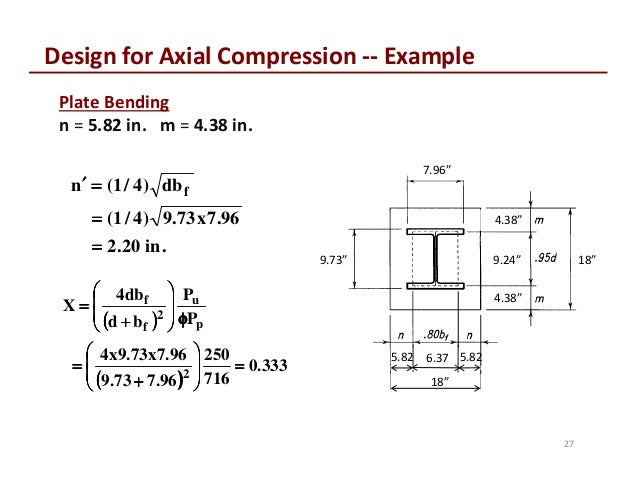
Steel column cap plate design example. Design a base plate given that the column dead load is 100 kips and live load is 150 kips. Example 7 designing the lightest steel column based on given loads effective length and yield stress. A w10 x 49 column is supported by a concrete pier whose top surface is 19 inches x 19 inches. When a concentrated tensile or compressive force acts on the end of a round or rectangular hss column with a cap plate and the force is in the direction of the hss axis the walls of the hss member could fail in sidewall yielding with consideration of shear lag.
Practical design and detailing of steel column base plates table of contents description page no. The design examples provide coverage of all applicable limit states whether or not a. Example 6 designing a steel column based on given dead and live loads effective length and yield stress. Base plate material is a36 steel and concrete compressive strength is 3 ksi.
Detailing requirements design procedures worked examples and. In addition to the examples that demonstrate the use of the aisc manual tables design examples are provided for connection designs beyond the scope of the tables in the aisc manual. The design examples provide coverage of all applicable limit states whether or not a particular limit state controls the design of the member or connection. Please contact the structural engineer involved with your project before you order your steel to make sure you have the correct cap and base plates for your columns.
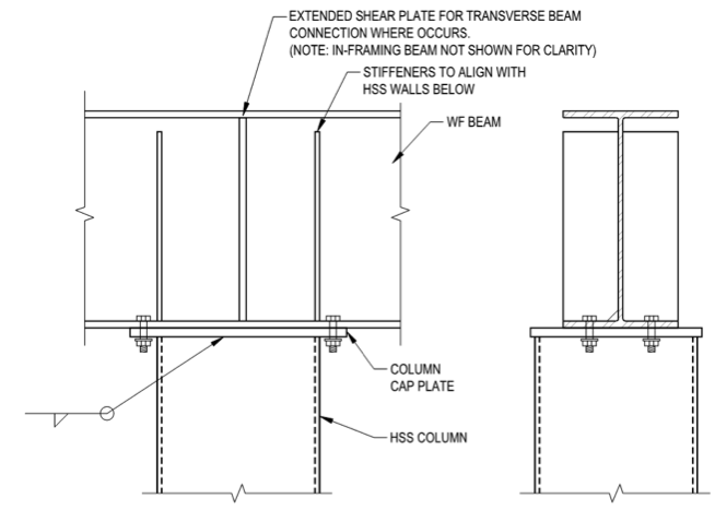
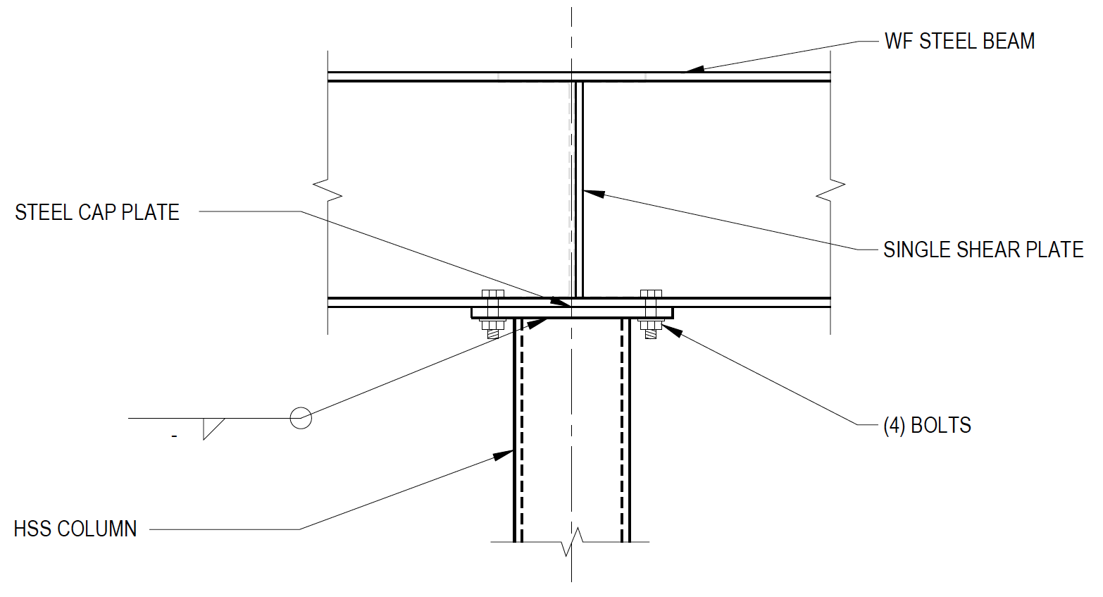
Most engineers will specify a bolted connection between the cap plate and steel beam to comply with osha regulations and for ease of construction and inspection. 1 0 2 0 3 0 4 0 5 0 6 0 introduction 2 1 1 preface 2 1 2 purpose 2 1 3 organization 2 design guidelines for materials and fabrication 2 1 materials 2 1 1 anchor bolts and nuts 2 1 2 plates. If cap and base plate splices are located away from a point of restraint special consideration should be given to ensuring adequate stiffness so that the member design is not invalidated.


